|
Kategorie:CC-by-sa
Zur Navigation springen
Zur Suche springen
Medien in der Kategorie „CC-by-sa“
Folgende 200 Dateien sind in dieser Kategorie, von 468 insgesamt.
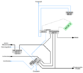
(vorherige Seite) (nächste Seite)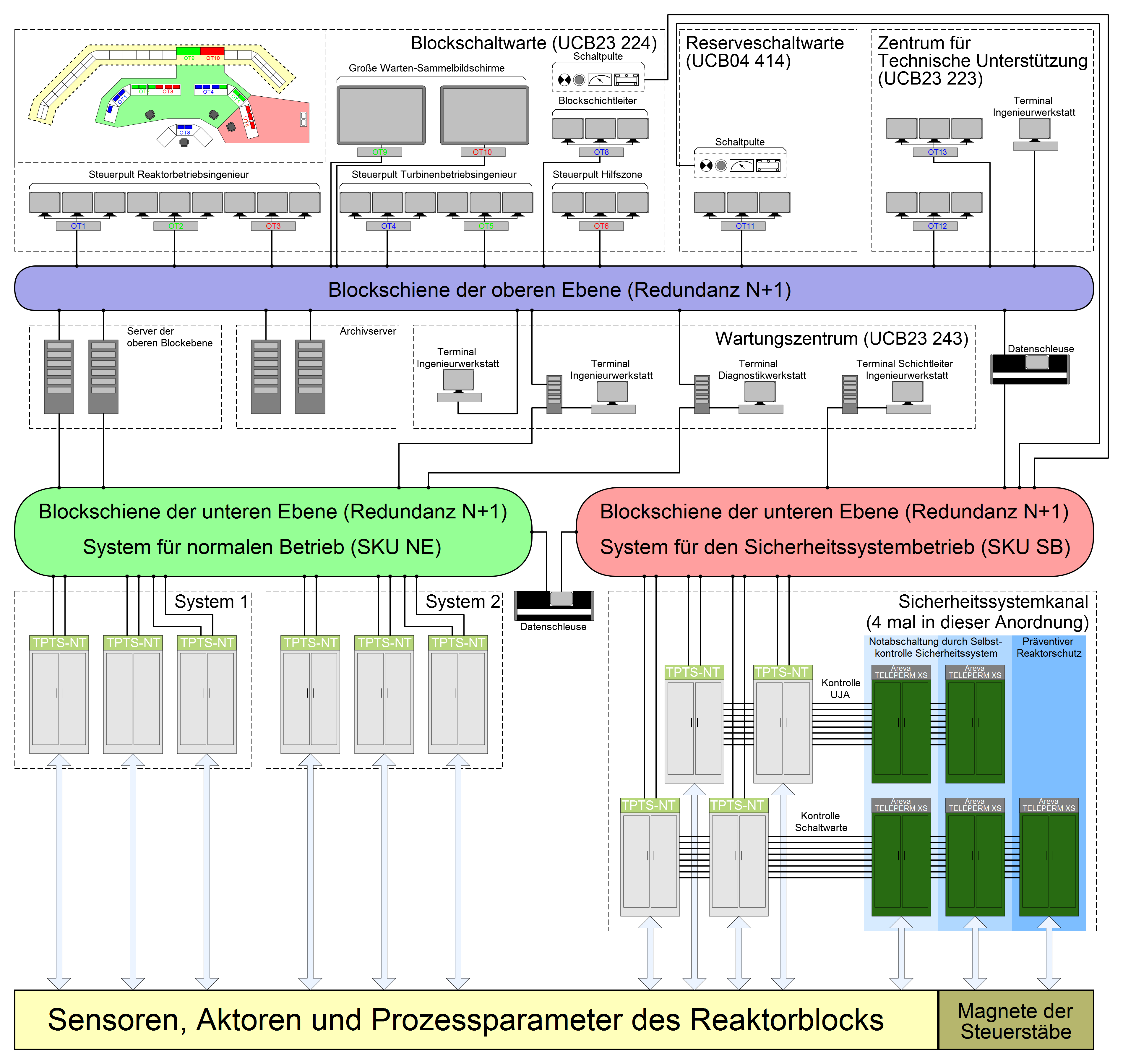 AES-2006 Leittechnik.svg 3.800 × 3.600; 123 KB
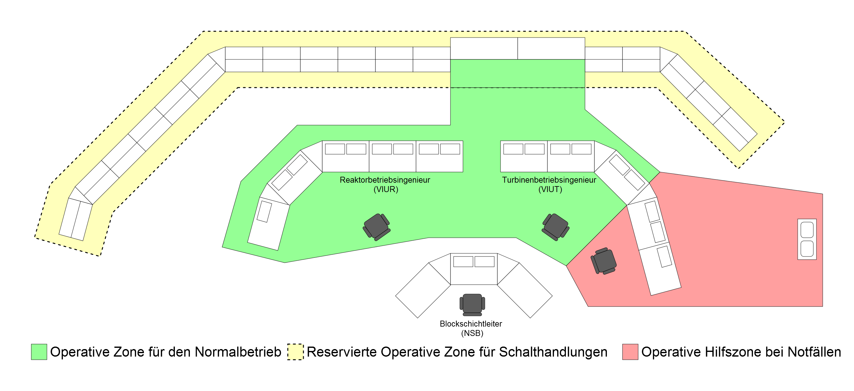 AES-2006 Schaltwarte.svg 2.730 × 1.250; 20 KB
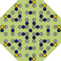 Al-Kibar Kern.png 808 × 808; 18 KB
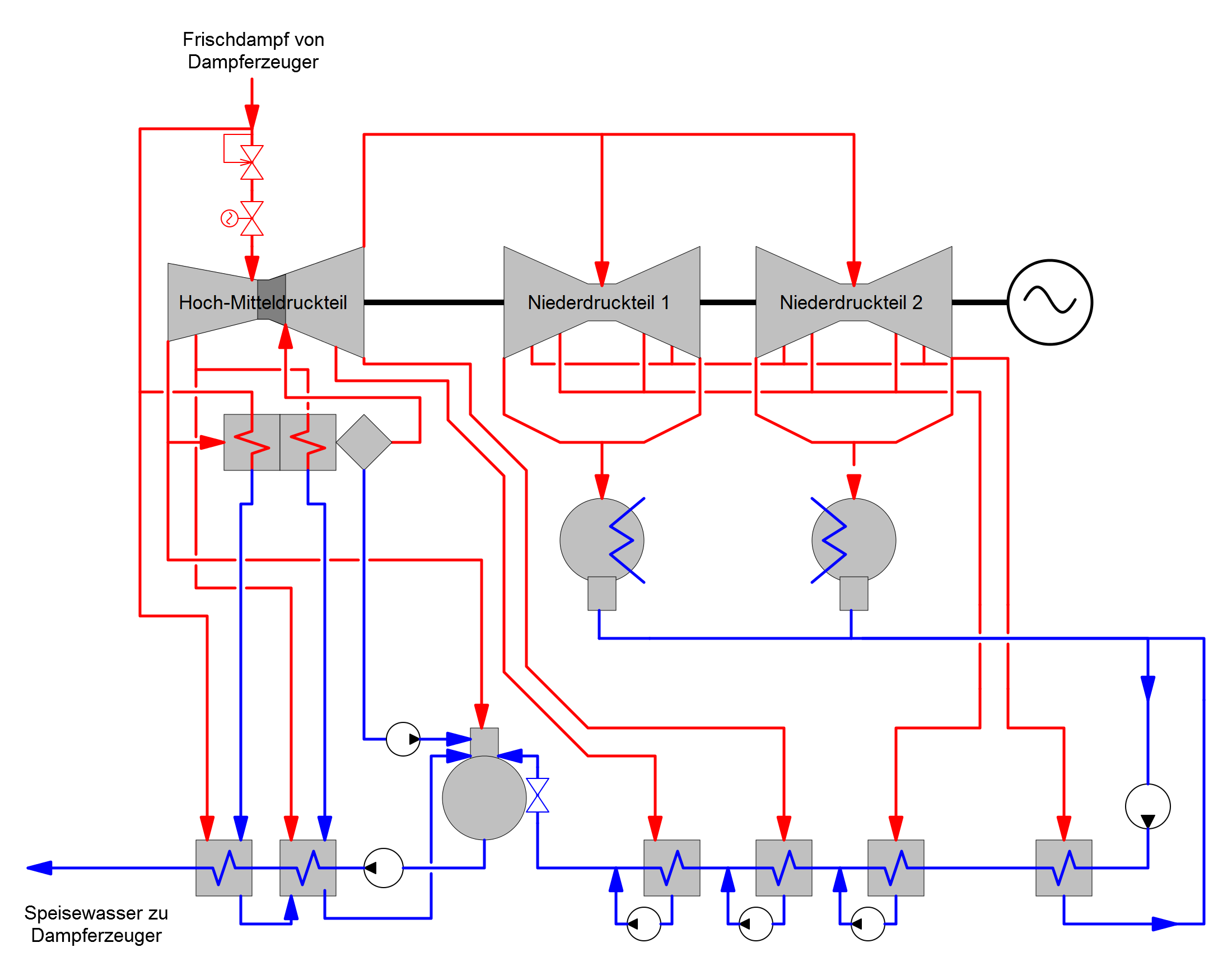 Alstom ARABELLE 1200 MW.svg 2.200 × 1.750; 26 KB
 Anschaltung Blösien.svg 5.200 × 3.680; 12 KB
 Anschaltung Bäumchen.svg 5.200 × 3.680; 13 KB
 Anschaltung Delitzsch 1982.svg 2.890 × 2.330; 9 KB
 Anschaltung Delitzsch.svg 2.890 × 2.330; 9 KB
 Anschaltung Hohenwarthe.svg 2.570 × 4.030; 10 KB
 Anschaltung Oberböhmsdorf.svg 3.650 × 2.100; 9 KB
 Anschaltung Paulskopfwarte.svg 5.200 × 3.680; 13 KB
 Anschaltung Rietzmeck 1982.svg 2.520 × 1.860; 6 KB
 Anschaltung Rietzmeck.svg 2.500 × 2.240; 7 KB
 Anschaltung Tuchen.svg 3.510 × 3.100; 10 KB
 Anschaltung Wildenhain.svg 3.280 × 3.290; 8 KB
 AP1000 Containmentleck.png 452 × 828; 9 KB
 AP1000 IVR.png 966 × 1.532; 21 KB
 AP1000 Kernladung.png 1.260 × 1.260; 10 KB
 AP1000 PCCS.png 452 × 828; 10 KB
 AP1000 R15 R18 Dach.png 899 × 281; 6 KB
 AP1000 RDB Instrumentation.png 652 × 1.411; 11 KB
 AP1000 RDB Umlauf.png 652 × 1.411; 29 KB
 AP1000 RDB.png 652 × 1.411; 11 KB
 AP1000 Shield Building.png 452 × 828; 7 KB
 AP1000 UJA 107-2.png 452 × 452; 8 KB
 AST Schema Subsysteme.svg 2.330 × 1.500; 72 KB
 AST Schema Vereinfacht.svg 2.330 × 1.200; 34 KB
 AST-200 Schema.svg 2.600 × 1.200; 61 KB
 AST-500 Brennelement bemaßt.svg 1.450 × 1.300; 39 KB
 AST-500 Brennelement.svg 2.760 × 2.400; 18 KB
 AST-500 Schema.svg 2.750 × 1.700; 80 KB
 AST-500 Transiente Fernwärmebruch.svg 800 × 900; 8 KB
 AST-500 Transiente Hauptwärmesenke.svg 800 × 900; 8 KB
 AST-500 Transiente Steuerstäbe ausfahren bei Stillstand.svg 800 × 800; 9 KB
 AST-500 Transiente Steuerstäbe ausfahren.svg 700 × 800; 9 KB
 Betriebsdiagramm SPX.svg 2.050 × 750; 23 KB
 BN-350 Kern.svg 3.270 × 3.110; 126 KB
 BN-600 Kern.png 1.686 × 1.615; 63 KB
 BN-800 China Kern.svg 3.840 × 3.930; 210 KB
 BN-800 Hybrid Kern 1.svg 3.840 × 3.930; 211 KB
 BN-800 Hybrid Kern 4.svg 3.840 × 3.930; 211 KB
 BN-800 Kern.png 1.861 × 1.873; 88 KB
 BN-800 MOX Kern.svg 3.840 × 3.930; 211 KB
 BN-800 plot.png 2.610 × 1.256; 16 KB
 BN-800 Schema.svg 5.250 × 3.000; 150 KB
 BN-800 vergleich plot.png 2.840 × 2.859; 60 KB
 BN-800M A-A.png 1.201 × 1.191; 40 KB
 BN-800M B-B.png 1.147 × 1.191; 39 KB
 BN-800M plot.png 2.277 × 1.109; 13 KB
 Bohrloch Gomel-30.png 336 × 1.171; 16 KB
 Borssele 2 Plot.svg 3.260 × 1.180; 4 KB
 Borssele B site.svg 1.375 × 1.375; 3,99 MB
 Borssele Datennetz 1982.svg 1.800 × 1.200; 200 KB
 BR-1200 Kern.svg 2.890 × 2.700; 103 KB
 Brennelement Hualong One.svg 2.880 × 20.456; 130 KB
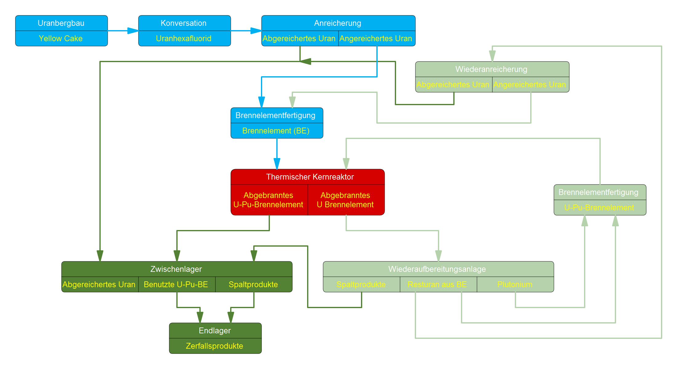 Brennstoffkreislauf 1.svg 2.200 × 1.200; 15 KB
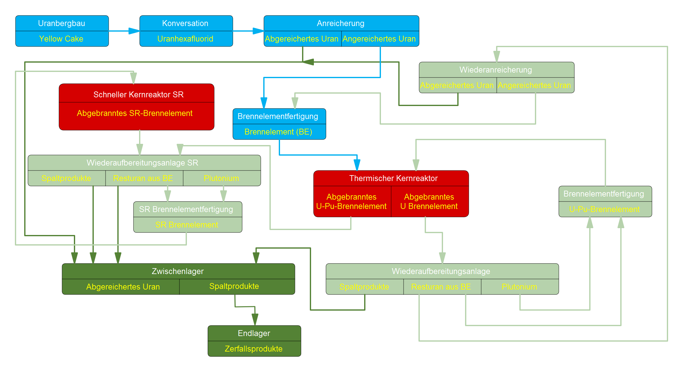 Brennstoffkreislauf4.SVG 2.200 × 1.200; 25 KB
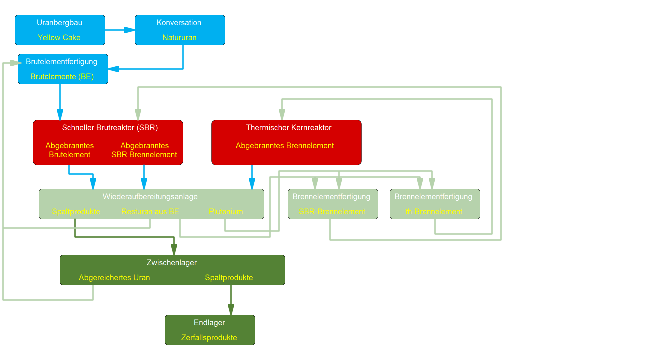 Brennstoffkreislauf5.SVG 2.200 × 1.200; 14 KB
 BREST-OD-300 Brennstab Schnitt.svg 1.060 × 1.060; 3 KB
 BREST-OD-300 Kern.svg 2.120 × 2.030; 60 KB
 BREST-OD-300 Schema.svg 4.200 × 1.800; 59 KB
 BWRX-300 CCWS.svg 850 × 500; 4 KB
 BWRX-300 HPIS.svg 3.100 × 7.100; 20 KB
 BWRX-300 ICS.svg 1.700 × 780; 38 KB
 BWRX-300 PCCS.svg 650 × 600; 4 KB
 BWRX-300 PSWS.svg 1.050 × 520; 5 KB
 CAP1000 Shield Building.png 452 × 843; 8 KB
 CDF Borssele 1997.svg 1.900 × 990; 370 KB
 CDF EBO V1.svg 1.900 × 990; 27 KB
 CDF V 1.11 Pointermap.svg 2.000 × 990; 192 KB
 CDF WWER-1200.svg 2.300 × 990; 34 KB
 CEFR Kern.png 1.311 × 1.443; 42 KB
 CFR-1000 Kern.png 1.886 × 1.959; 83 KB
 CFR-600 Kern.png 1.711 × 1.701; 67 KB
 CGN Auxiliary Feed-water System.svg 2.300 × 2.100; 356 KB
 CGN Containment Filtration and Exhaust System.svg 2.100 × 1.100; 179 KB
 CGN Containment Spray System.svg 1.540 × 1.580; 222 KB
 CGN Emergency Boron Injection System.svg 1.550 × 1.850; 178 KB
 CGN Extra Cooling System.svg 2.600 × 1.520; 451 KB
 CGN Hualong Plot.svg 2.650 × 2.150; 5 KB
 CGN Reactor Cavity Injection and Cooling System.svg 1.740 × 1.100; 283 KB
 CGN Safety Injection System Accumulators.svg 1.550 × 2.100; 236 KB
 CGN Safety Injection System MD-Injection.svg 1.550 × 2.100; 236 KB
 CGN Safety Injection System ND-Injection.svg 1.550 × 2.100; 236 KB
 CGN Secondary Passive Heat Removal System.svg 1.750 × 1.800; 284 KB
 ChAES-4 Eigenbedarfsversorgung Auslaufversuch.svg 5.200 × 2.250; 78 KB
 ChAES-4 Eigenbedarfsversorgung.svg 3.500 × 2.200; 55 KB
 China DWR Entwicklung.svg 2.350 × 1.750; 1,69 MB
 CNNC Auxiliary Feed-water System.svg 1.850 × 1.500; 146 KB
 CNNC Containment Spray System.svg 1.530 × 1.580; 216 KB
 CNNC Hualong Plot.svg 2.640 × 1.680; 19 KB
 CNNC Passive Containment Cooling System.svg 1.920 × 1.520; 218 KB
 CNNC Reactor Cavity Injection and Cooling System.svg 1.630 × 1.360; 226 KB
 CNNC Safety Injection System Accumulators.svg 1.550 × 2.200; 203 KB
 CNNC Safety Injection System MD-Injection.svg 1.550 × 2.200; 204 KB
 CNNC Safety Injection System ND-Injection.svg 1.550 × 2.200; 203 KB
 CNNC Secondary Passive Heat Removal System.svg 1.750 × 1.580; 216 KB
 Dongfang TC-F72 1828 mm.svg 2.700 × 1.730; 122 KB
 Eigenbedarf CGN HPR1000 Netzverlust.svg 9.250 × 7.600; 3,2 MB
 Eigenbedarf CGN HPR1000 SBO Mobil.svg 9.250 × 7.600; 3,2 MB
 Eigenbedarf CGN HPR1000 SBO.svg 9.250 × 7.600; 3,2 MB
 Eigenbedarf CGN HPR1000.svg 9.250 × 7.600; 3,2 MB
 Eigenbedarf UK-HPR1000 Netzverlust.svg 9.250 × 7.600; 3,16 MB
 Eigenbedarf UK-HPR1000 SBO Mobil.svg 9.250 × 7.600; 3,16 MB
 Eigenbedarf UK-HPR1000 SBO.svg 9.250 × 7.600; 3,16 MB
 Eigenbedarf UK-HPR1000.svg 9.250 × 7.600; 3,16 MB
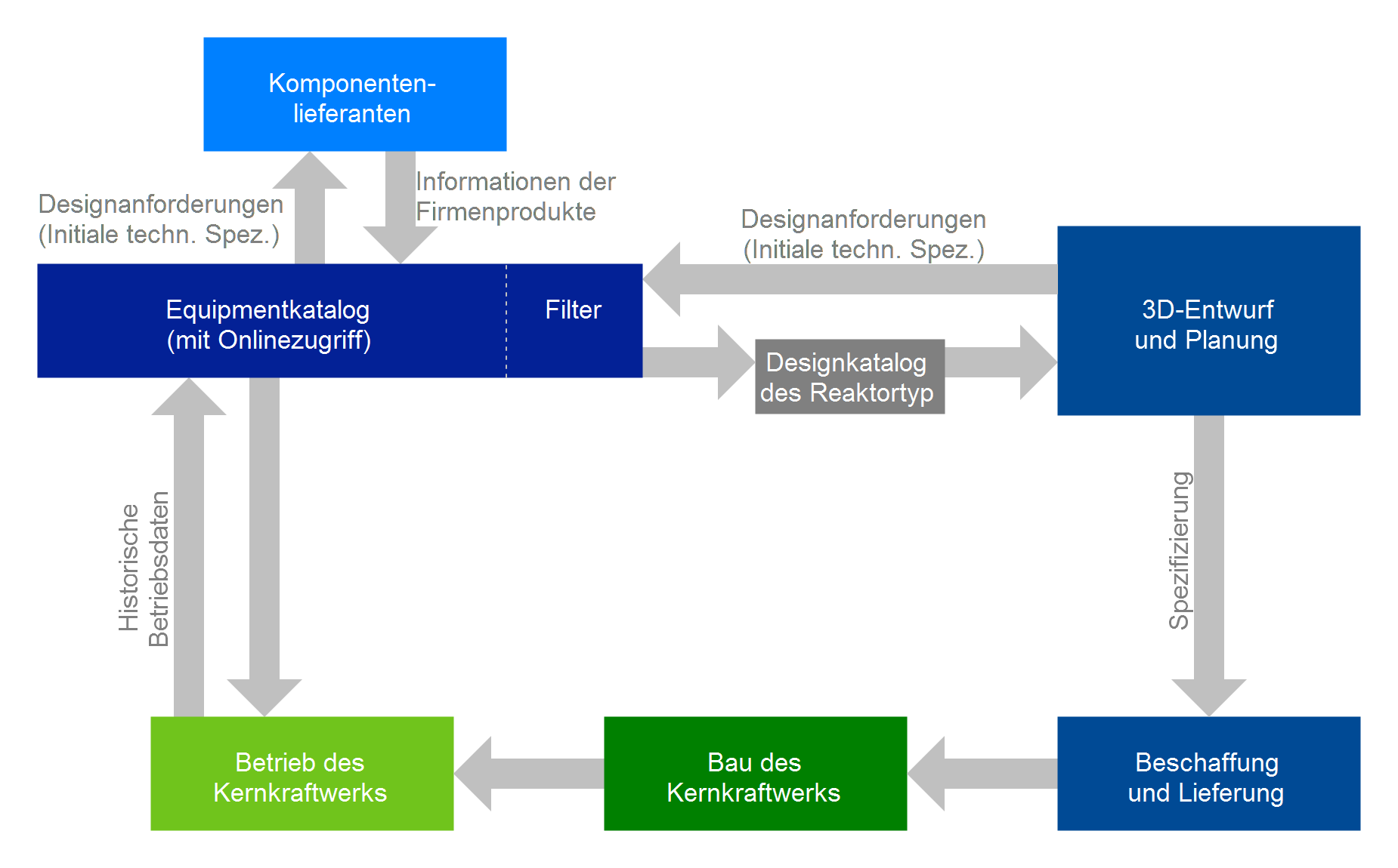 Equipmentkatalog NIAEP.svg 1.850 × 1.150; 9 KB
 Fernwärmenetz Blösien.svg 1.280 × 1.640; 5 KB
 Fernwärmenetz Bäumchen.svg 990 × 1.850; 5 KB
 Fernwärmenetz Delitzsch.svg 2.370 × 1.490; 4 KB
 Fernwärmenetz Hohenwarthe.svg 1.890 × 2.190; 7 KB
 Fernwärmenetz Ostrava-Karvina Prognose 2000.svg 3.040 × 2.640; 19 KB
 Fernwärmenetz Paulskopfwarte.svg 1.820 × 1.640; 5 KB
 Fernwärmenetz Rietzmeck.svg 620 × 900; 2 KB
 Fernwärmenetz Sülzenbrücken.svg 1.490 × 1.490; 3 KB
 Fernwärmenetz Tuchen.svg 1.370 × 1.610; 4 KB
 Fernwärmenetz Wildenhain.svg 1.100 × 2.200; 4 KB
 Flaechenvergleich 2.png 803 × 301; 6 KB
 Flaechenvergleich.png 602 × 300; 6 KB
 FMCRD Hydraulikkontrollsystem.svg 1.170 × 800; 13 KB
 FMCRD Schema Elektrisch.svg 2.100 × 4.400; 20 KB
 FMCRD Schema Hydraulisch.svg 6.200 × 7.100; 38 KB
 FMCRD Schema.svg 2.500 × 3.270; 13 KB
 Funktionsdiagramm AM-1.svg 2.440 × 1.230; 41 KB
 Funktionsdiagramm KRB-A.svg 1.200 × 860; 21 KB
 General Electric BWR Entwicklung.svg 1.311 × 443; 1,53 MB
 Graphit RBMK Kursk-5 top.svg 5.500 × 2.900; 11 KB
 Graphit RBMK top.svg 5.500 × 2.900; 8 KB
 Grundriss JK-PWR.png 3.186 × 1.740; 48 KB
 Grundriss Konvoi.png 2.125 × 2.320; 34 KB
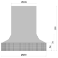 Heller Kühlturm 190-106.svg 2.450 × 2.450; 32 KB
 Hexagon 1.png 51 × 57; 392 Bytes
 Hexagon 2.png 51 × 57; 387 Bytes
 Hexagon 3.png 51 × 57; 394 Bytes
 Hexagon 4.png 51 × 57; 389 Bytes
 Hexagon 5.png 51 × 57; 387 Bytes
 HPR Atmospheric Steam Dump System.svg 1.470 × 1.190; 128 KB
 HPR Druckhalter.svg 2.600 × 1.450; 608 KB
 HPR Fast Depressurization System.svg 2.600 × 1.450; 609 KB
 HPR San'ao RPV High-point Venting System.svg 1.300 × 1.100; 206 KB
 HPR Taipingling RPV High-point Venting System.svg 1.300 × 1.100; 206 KB
 Hualong Brennelement Anordnung.svg 4.580 × 6.820; 185 KB
 Hualong Brennelement MOX Anordnung.svg 833 × 833; 31 KB
 Hualong Schema.svg 3.150 × 1.100; 61 KB
 Hualong Steuerstab.svg 939 × 2.835; 125 KB
 Icon FloatingNuclearPowerPlant-black.svg 75 × 75; 5 KB
 Icon FloatingNuclearPowerPlant-blue.svg 75 × 75; 5 KB
 Icon FloatingNuclearPowerPlant-green.svg 75 × 75; 5 KB
 Icon FloatingNuclearPowerPlant-grey.svg 75 × 75; 5 KB
 Icon FloatingNuclearPowerPlant-iceblue.svg 75 × 75; 5 KB
 Icon FloatingNuclearPowerPlant-red.svg 75 × 75; 5 KB
 Icon FloatingNuclearPowerPlant-white.svg 75 × 75; 5 KB
 Icon FloatingNuclearPowerPlant-yellow.svg 75 × 75; 5 KB
 Icon NuclearHeatingPlant-black.svg 75 × 75; 8 KB
 Icon NuclearHeatingPlant-blue.svg 75 × 75; 8 KB
 Icon NuclearHeatingPlant-green.svg 75 × 75; 8 KB
 Icon NuclearHeatingPlant-grey.svg 75 × 75; 8 KB
 Icon NuclearHeatingPlant-iceblue.svg 75 × 75; 8 KB
 Icon NuclearHeatingPlant-red.svg 75 × 75; 9 KB
 Icon NuclearHeatingPlant-yellow.svg 75 × 75; 8 KB
 Icon NuclearHeatingPlant.svg 75 × 75; 7 KB
 K-1200-6,8-25.svg 2.200 × 1.750; 38 KB
 K-1200-6,8-50.svg 2.900 × 1.950; 50 KB
 Kern AM-1.SVG 2.290 × 2.640; 29 KB
 Kern AP1000.png 1.260 × 1.260; 10 KB
 Kern Arkansas One-2 CEA Gruppen.svg 1.500 × 1.500; 46 KB
 Kern Arkansas One-2.svg 1.500 × 1.500; 31 KB
 Kern AST-500 Anreicherung.svg 1.160 × 1.110; 16 KB
 Kern AST-500 Sensorik.svg 1.160 × 1.110; 16 KB
 Kern AST-500.svg 1.160 × 1.110; 24 KB
 Kern BASF.png 651 × 651; 3 KB
 Kern BWR-6 218-624.svg 2.800 × 2.800; 141 KB
 Kern BWR-6 238-648.svg 3.000 × 3.000; 146 KB
 Kern BWR-6 238-732.svg 3.000 × 3.000; 167 KB
 Kern BWR-6 238-748.svg 3.000 × 3.000; 169 KB
 Kern BWR-6 251-800.svg 3.200 × 3.200; 182 KB
 Kern BWRX-300.svg 1.800 × 1.800; 54 KB
 Kern Calvert Cliffs.svg 1.700 × 1.700; 38 KB
 Kern Fort Calhoun-1 CEA Gruppen.svg 1.300 × 1.300; 32 KB
 Kern Fort Calhoun-1.svg 1.300 × 1.300; 23 KB
 Kern Goesgen.png 751 × 751; 4 KB
 Kern Hualong CNNC CR-Gruppen.svg 531 × 531; 175 KB
 Kern Hualong CNNC.svg 531 × 531; 22 KB
 Kern Hualong One Instrumentierung.svg 531 × 531; 26 KB
 Kern Hualong One Koordinatensystem.svg 1.700 × 1.700; 69 KB
 Kern Hualong Standard CR-Gruppen.svg 531 × 531; 205 KB
 Kern Hualong Standard.svg 531 × 531; 22 KB
 Kern IPWR.png 651 × 659; 9 KB
 Kern KKU.png 751 × 751; 4 KB
 Kern Konvoi.png 751 × 751; 4 KB
 Kern KS-150 C-05.svg 3.750 × 3.750; 29 KB
 Kern KS-150 H-05.svg 3.750 × 3.750; 29 KB
 Kern KS-150.svg 3.750 × 3.750; 29 KB
 Kern KWB-A.png 751 × 751; 4 KB
 Kern KWB-B.png 751 × 751; 4 KB
 Kern KWU DWR-600 MWe.png 651 × 651; 3 KB
 Kern Millstone-2 CEA Gruppen.svg 1.700 × 1.700; 51 KB
 Kern Millstone-2.svg 1.700 × 1.700; 38 KB
 Kern Monju.PNG 1.111 × 1.013; 27 KB
 Kern Palisades-1 CEA Gruppen.svg 1.600 × 1.600; 58 KB


